
This example is from 2002, by IBM and RDA Corp, published at https://www.ibm.com/developerworks/rational/library/content/03July/2000/2000/2000_RDAEStoreAbbrevSAD.doc.
I'm happy with this style of S.A.D, but there some things I would change if I was in an organisation that produced this kind of document. Broadly, I would related the views back to the structure of the 4+1 approach, rather than simply listing 6 apparently unrelated views.
- Put the “+1” back in, in the form of a Use Case and Context View.
- Add a Domain Model & Glossary to to the Logical View. To my mind, these are the centrepiece of the Logical View.
- Notice that the Security View is more a narrative of how the requirement is met than it is a model of the system. I would follow Rozanski & Wood's terminology and call it the Security Perspective, and/or put it in a Quality Attributes section after the views.
Also, I don't believe that Security is the only important Quality Attribute. I'd add sections for them. - Make the Data View a child view of the Logical View. In this example document, physical database details have been explicitly excluded. This suggests to me that the database is owned by a different team to the team developing this system, and the Data View is effectively the “interface” provided by the database team to the team developing this system. In that case, I would show the database on a Context diagram as an external dependency.
- I would rename Implementation View back to Development View, and use it to
- link to to the CI/CD pipeline, which in my mind entirely replaces all technical detail that you might put in the Implementation View.
- Discuss the human factors, team organisation and ownership. The interesting question about the top-level packages is, who owns them?
“
1 Introduction
The architecture of a software system requires six distinct views, each view focusing on different aspects of the system. Its purpose is to communicate the major components of the system, how it is structured, the system process flows, and major interfaces. From a high level, the goal is to examine the system from several different perspectives, each providing a different “view” in order to capture all critical system features. A brief description of the six architecture views is provided as follows:
Deployment View – This view documents the physical topology of the system modeled in the Deployment Model. It includes each computer in the implementation and describes how they are interconnected. The configuration for each node is also specified – Operating system, databases, Commercial off-the shelf (COTS), and custom applications.
Logical View – The logical view documents the Design Model, which defines the layers of the application and the primary classes within each layer. The system architect identifies patterns of functionality and creates common mechanisms to provide this functionality to several areas across the application.
Data View – Classes in the logical view are classified as transient or persistent. The persistent classes are mapped to structures on disk, usually into a combination of rows in a relational database. An entity-relationship data model describes the database schema. This view also communicates how the Object-Oriented classes are mapped to the relational tables.
Process (Concurrency) View – This view focuses on the concurrency aspects of the system and how they contend for shared resources (i.e., transaction semantics, etc.). The process view documents the independent threads of execution within the system and describes how they communicate. It also lists the resources in contention by these threads and the transaction model for maintaining integrity with these resources.
Implementation View – This view maps the classes in the Logical View to physical source files and combines the files into deployable components. The implementation view also tracks the dependencies among the components.
Security View – This view focuses on how the system identifies end users, grants authorization to them based on their identity, ensuring integrity of the system and of the data and properly tracking and auditing of system activity.
Note: This is a brief overview of the architecture. The complete eStore SAD is included in the download.
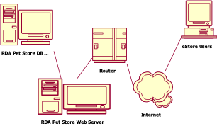
2 Deployment View
The configuration view presents the topology and its physical and logical connections.
3 Logical View
The logical view presents the core design of the system. It presents the primary classes that collaborate to implement the system functionality. It contains the following subsections:
3.1 Three Software Layers
The application is structured along three distinct layers – UI Layer, Business Layer and Data Layer.

UI Layer: Responsible for authentication, presentation
and managing session state.
Business Layer: Exports the business objects defined in the Solution Model class analysis. Maintains no knowledge of presentation. Insulates the UI Layer from database design. Responsible for complex business rule logic.
Data Layer: Responsible for managing persistent data and transactions. Maps business objects to physical relational tables. Responsible for data integrity, transactions and data intensive business rules such as unique name on a column.
3.2 Business Layer Interface
The following diagram illustrates the classes and their relationships exported from the business layer to the presentation layer.
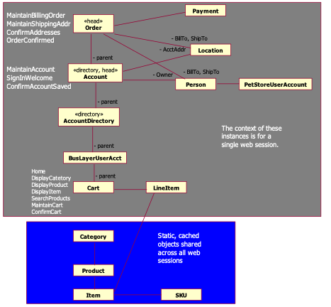
Figure 1: UI Session Stack Class Diagram
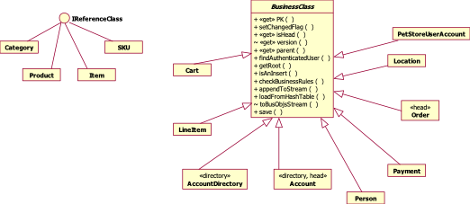
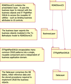
3.3 Business Layer Implementation
Pet Store’s business layer is implemented by leveraging the services provided by IT FlightPlan’s Software Library. The business classes exported by the business layer are either BusinessClasses or ReferenceClasses. IT FlightPlan’s Software Library exports a BusinessClass base, abstract class and an IReferenceClass interface. The following diagram shows how the classes in the business layer are implemented – the session BusinessClasses inherit from BusinessClass while the cached classes implement the IReferenceClass interface.
4 Data View
The Database Model is presented as a logical view, physical view and data dictionary. The logical data model is included in this overview.
4.1 E/R Model
4.1.1
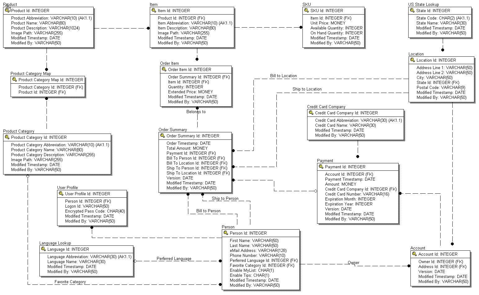
Logical View
5 Process View (Concurrency)
The Process View focuses on the parallel processing aspects within the system. eStore deals with concurrency in two distinct areas -
- The CPU/process/thread design
2. Transaction design for shared resources,
A. Records in the PetStore database – single data source
B. Updates to PetStore database and the Credit Authorizer
C. Shared objects in memory
5.1 CPU/Process/Thread Design
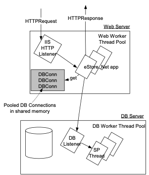
This diagram shows the major threads and context switches involved with processing a web request. IIS allocates a pool of worker threads to process HTTP requests and posts.
5.2 Transaction Design
5.2.1 PetStore Database transactions
All transactions are encapsulated within a call from the BusinessLayer to a stored procedure. Any SQL errors within a stored procedure force a rollback and the error is raised to the BusinessLayer.
Account data integrity is maintained through optimistic concurrency. A unique version timestamp is returned with each head Account object.
5.2.2 Updates to PetStore database and the Credit Authorizer
There is one point in the application where there are two distinct data sources, so this leads to a critical region in the code. ConfirmAddresses invokes CreditAuthorizer to charge the customer’s credit card. If successful, it returns a credit authorization code, which is stored in the Payment when the Order is saved. We have an exposure in the case where the charge is successful, but Order.save() fails. CreditAuthorizer does not support two-phased commit transactions, so RDA Pet Store will continue to reconcile its daily charges with the Credit Authorizer at the close of each business day.
5.2.3 Shared Objects in Memory
The static reference objects that are shared across all sessions have only one instance per web server. All sessions refer to this single instance. Since these classes are loaded when the application starts and are not modified, semaphores are not required for synchronization.
6 ImplementationView
The implementation view describes how the software is physically contained in files and how files combine to form components. At the highest level, the application is comprised of packages.
The 3 layers outlined in the Logical View (UI, Business and Data) are implemented with the above packages as follows –
UI Layer:
- RDAEStore[CS, VB] - all aspx, code behinds, images and Pet Store UI utilities
· ITFlightPlanSWLib - generic UI utilities to bind/unbind attributes to UI controls
Business Layer:
- BusinessLayer[CS, VB] - all of the Pet Store business classes
· ITFlightPlanSWLib packages – reusable mechanisms the provide persistence and error handling\
Data Layer:
· DataLayer – the Pet Store tables, stored procedures and reference data
· ITFlightPlanSWLib – Generic wrapper interface to access ADO
7 Security View
The security view describes how the system implements the security requirements specified in the Detailed Spec. Security design is presented in the following sub-areas.
ü User Identification & Authentication – How does the system identify users and verify it is them?
ü Authorization – Once authenticated, who is allowed to do what?
ü Data Integrity and Privacy – Ensure the integrity of the data is not compromised.
ü Non-repudiation and Auditing – Ensure the end user cannot cover up their tracks. Record access to the data so we know who’s done what.
7.1 User Identification & Authentication
- eStore uses ASP.Net Forms authentication to authenticate users.
- UserIDs and passwords are stored in the RDAPetStore database. Passwords are first “sha1”, 40-byte encrypted before being stored in the database.
- The eStore application itself authenticates with its own SQL Server userID. The ID and password is stored in the web.config file. The only the database objects granted to the eStore userID are execute grants to the eStore stored procedures.
7.2 Authorization - Data Entitlement
eStore uses a single stored procedure – getAccountForUserID – to fetch the account information for a particular user and stores it in the session stack.
Since the authenticated user contained in the session stack, eStore relies on the integrity of .Net sessions to ensure that users can only access their own accounts.
7.3 Data Integrity and Privacy
V1.0 of RDA Pet Store provides minimal protection of data. Passwords are encrypted before they are stored in the database.
Extending Pet Store to be more secure, we would use SSL to transmit password and credit card information.
7.4 Non-repudiation &Auditing
Each table in the database provides last modified by and last modified timestamp columns. The authenticated userID parameter on the save stored procedure is set in these columns on all inserts and updates.
One thought on “Other Examples of Software Architecture with UML (2002)”
Comments are closed.